This is now redundant because of the layout re-configuration but the servo testers will be re-purpose in other locations in the future
Because I was having some issues with my Aristocraft and LGB manual points;
- The LGB points I had would not throw properly with a manual lever and
- The Aristocraft ones did not have any levers at all
I have decided to operate them with servo motors using Simple Servo Testers as described by Dave Bodnar of "Trainelectronics".
http://www.trainelectronics.com/Servo-simple-controller/index.htm
A copy of the "Simple Inexpensive Servo Controller" article has been reproduced on a separate page under "Servo Controlled Points" heading with Dave Bodnar's permission.
Simple Inexpensive Servo Controller
To power the servos I am using a 12V 5AHr Sealed Lead Acid (SLA) battery with a 5V 3A Step Down Buck Converter to provide a 5V bus.
5V 3A Step Down Buck Converter.
The SLA is kept charged by a solar panel via a Charge Controller which provides Over and Under Voltage protection.
Panel;
Charge Controller;
BLOCK DIAGRAM;
 |
| Servo Wiring Block Diagram |
I decided against using the 12V directly off the battery, because putting a load in parallel with the Buck Converter input may affect it's operation.
If I want to add a 12V bus in the future I can simply buy a smaller capacity battery, (AHr) another panel (5W) and charge controller to run the 5V 3A bus but I do not have plans to run any 12V equipment at the moment.
SOLAR PANEL;
 |
| Solar Panel |
 |
| Solar Panel Mount |
CHARGE CONTROLLER;
 |
| Charge Controller showing Lights (Power Green; Charge Red) |
CHARGE CONTROLLER/BATTERY INSTALL;
 |
| Charge Controller and Battery Enclosures |
SERVO;
I am using waterproof servos mounted under the base board with the top protruding through a hole cut in the baseboard.
This allows the servo actuator horn to be on the same plane as the point throw bar.
 |
| Mock up of the servo mounting |
 |
| Servo mounted under basrboard |
 |
| Servo top protruding through baseboard |

Control Rod and Clevis Pin
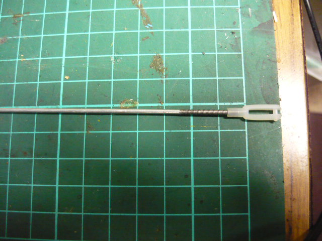
 |
| Linkage Stopper |
TRIM POT;
To determine the distance the points blades travel; I used a 5K ohm "trim pot" (a small variable resistor) instead of the 4.7K ohm fixed value resistor. This allows me to fine tune the blade movement without having to change fixed value resistors.
UPDATE March 2025;
After a while I found that the 5Kohm trimpot was not a high enough value to full "fine tune" some servos so I changed it to a 10K ohm one.
This gave me a bigger range of adjustment at the top end.as 5K ohm was close to the 4.7K ohm used originally but with resistor tolerances adjustment this was at the extreme end.
 |
| Trimpot |
CONTROL SWITCH;
The control switches are waterproof as used in marine applications and are mounted on a control panel made from steel "C" purlin, which forms an integral part of the base board support/fascia board.
 |
| Switch |
TESTER MODIFICATION and ENCLOSURES;
Servo Testers were modified to fit the trimpot and switch input.
Each of the servo testers will be housed in an enclosure made from a plastic food container, with a seal-able lid, secured under the baseboard out of the weather and as close as possible to the points.
 |
| Line Drawing of Enclosure Components |
The pictures below show the modification wiring in closer detail;
- Power input on the Right,
- Servo output on the Left and
- Control switch input at the Bottom,
- and the enclosure fitment.
(When looking from the front.)
All cables going into the enclosure enter from the bottom through a cut down piece of irrigation fitting, to maintain waterproof integrity all holes (including mounting screws) will be sealed with bathroom silicone sealant.

 |
| Servo Tester enclosure mounted under baseboard |
The servo tester has 3 outputs for connecting servos, this has come in handy because I have connected 2 servos to one tester so that I can throw 2 sets of pints at the same time in a crossover.
I was planning on using a tester for each set of points but when the order for the 12 points I want to control arrived, 2 were different to the other 10 (picture is of one of them, the others have red circuit boards). The issue was that at power up they drove the servos through a 90 degree arc before settling into the preset position.
This caused issues with bending the clevis pins, the use of linkage stoppers overcame this because the stopper pivots to let the link arm go over centre and return to the it's set position at start up.
The ability to control multiple servos from the one tester for 2 pairs of points and has allowed me to use the 10 testers that do not drive the servos to full travel at power up.
I did encounter an minor issue with running 2 servos off the one tester which was a difference between the 2, one servo was still driving while the other had finished moving, this led to feedback onto the 5V power line which caused other servos on the line to "twitch".
The issue was easily overcome by adjusting the linkages, the pot and the trimpot; all it took was a bit of 'tweaking' of the 3 adjustments to achieve a compromise, I called this a "Fine Adjustment".
This "Fine Adjustment" allowed the points to be adjusted up against the stock rail, so that they stay hard up against the rail and overcame the servos driving all the time indicated by them buzzing. This resulted in the servo drawing minimum, if any, current (so low it was just measurable on the lowest current range of my multimeter).
I did this on all of the servos.
2 comments:
Hi, this is just what I have been looking for, thank you. Can you remember the values of the adjustable pot you used to adjust the throw of the points blades? The part replacing the 4.7 resister.
Thanks. Chris
The "trim pot" is a 5Kohm one
Post a Comment