Due to ground subsidence (possibly where a tree was removed 3 years ago) an area of my baseboard sagged by about 30mm or more, this led to a large dip in the track with wagons uncoupling as they passed over the high points at either end and rainwater ponding in the low points in the centre.
|
The Sag Amount (the rail is level)
|
Initially I thought I was faced with the prospect of digging up the centre supporting posts and raising the base board to level it off.
Further inspection revealed that the lattice frame supporting the area had bowed in the middle due to the centre supports sinking so the whole section would require replacement. This looked like turning into a major bit of work.
 |
Lattice section that sagged
|
After a bit of thinking I came up with the idea of leaving everything in place and building an embankment using concrete render across the area which would raise the track and make the it level.
This is how I did it;
I started by obtaining a level for the track using a couple of string lines I then leveled up the track using spacer blocks.
This now let me draw the outline of my embankments

Brown areas for a dry creek bed
Green areas for artificial turf
Red areas for embankments built from acrylic render
Using House Render
To save the amount of render needed and to reduce the weight I put in a couple of low bridges this will allow the water to run under the track and into drainage hole drilled through the baseboard. In these holes I put in some wicks to break up the water surface tension at the side of the holes and allow the water to flow down them into the garden below.
Bridges
For the bridge abutments I used builders vinyl moulding.
 |
Vinyl Bridge Abutment
|
To give a bit of character to the bridges I decided to make some veneers to attach to the abutments to give a stone look.
 |
Bridge Abutment
|
 |
Stone Texture Detail
|
These were drawn using Tinkercad, the stone texture design came from the shapes library Community area in Tinkercad (search "stone wall").
The design is for a castle but I just "cut" the crenellations off.
There is another without mortar that can be found by searching "brick wall" in the same area
For the piers
which will hold the aluminium track support beams I designed them in
Tinkercad and 3D printed them.
 |
Pier Front View
|
 |
Pier Oblique View
|
To support the rail I fitted rail supports made from 10mm aluminium U shaped channel fitted to the abutments and piers by cutting channels in them to allow them to slot in.
 |
| Bridge Rail Supports |
 |
| Bridge Rail Supports |
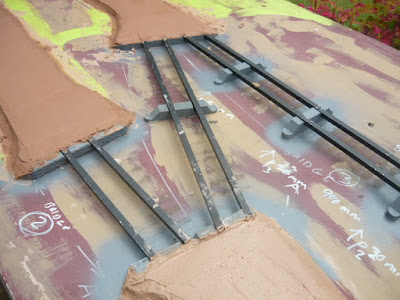 |
| Bridge Rail Supports |
 |
Bridges with track laid
|
 |
Close Up of Pier with Track laid
|
Embankments
After the bridges were built the embankments were laid and shaped using Acrylic Render .
 |
Render Embankment
|
 |
| Render Embankment with Bridge Rail Supports |
 |
| Render Embankment with Bridge Rail Supports | |
Track re-laid
After the render had set and hardened the rail was put back and secured in place using screws.
 |
Track re-laid
|
 |
Track re-laid
|
Finalising the scene.
To finish off the scene Artificial Turf, Gravel and Ballast were laid.
Artificial Turf
The artificial turf was bought at a discount store it came in a 3 metre roll 1 metre wide.
Gravel
The area simulating the "swamp/dry creek bed was painted with a tan coloured base coat of paint, onto this diluted exterior PVA glue was sprayed, then gravel was sprinkled over the area and finally another spray of PVA diluted with water with a few drops of dish-washing detergent added (sometimes referred to as "Wet Water") to break up the surface tension and allow the glue to run between the grave.
The "banks" of the creek were lined with larger sized gravel to define the edge.
 |
Creek Bed Painted
|
 |
| Creek Bank Close Up |
 |
Creek Bed Gravel
|
Ballast
The ballast I use is 7mm Blue Metal rock bought at a local landscape suppliers.
This is glued down using the same method as described above to lay the gravel.
 |
Abutment showing Gravel and Ballast
|
Wicks
To carry water down through the baseboard at the low point holes were drilled through the baseboard and wicks put into them. These allow the water drain away quickly to prevent ponding.
 |
| Wicks |
 |
Wick Close Up (LP= Low Point)
|
Finished